


Amazing Vacuum Furnaces - Vacuum Brazing Technics
Amazing Vacuum Furnaces - Vacuum Brazing Technics
Key for Brazing Success
Successful vacuum brazing relies on proper technique as well as the correct materials and furnace capability to continuously control the brazing cycle (vacuum level, heating/cooling rates, temperature, time, and purity of quenching gases). Experience has shown that better than ninety percent of all brazing problems occur because of a violation of one of these basic fundamentals of brazing [1, 2, 4]:
- Properly designed braze joints, appropriate to the service condition to be encountered
- Appropriate cleaning and surface preparation of work pieces prior to brazing
- Proper joint fit up (gap clearance at brazing temperature, flatness, squareness, burrs, etc.)
- Right brazing filler metal (BFM) selection, as well as use of good BFM preparation and application practices
- Appropriate assembly and fixturing
- Properly designed vacuum furnace brazing cycle (brazing temperature and time, heating and cooling rates, etc.)
- Adherence to process standards requirements for specific control and maintenance of vacuum furnace equipment
- Knowledgeable inspection of finished brazed assemblies
Introduction
The American Welding Society defines brazing as “a group of welding processes” which produces coalescence of materials by heating to suitable temperature and using a filler metal having a liquidus above 840F (450C) and below solidus of the base metal. The filler metal is distributed between the closely fitting surfaces of the joint by capillary attraction. For brazing to occur, the following three criteria must be met:
- Parts must be joined without melting the base metal
- Brazing filler metal (BFM) must have a liquidus temperature above 840∞F (450∞C)
- The BFM must wet the base metal surfaces and be drawn into or held in the joint by capillary attraction
To achieve a good joint using any brazing process the following conditions must be met:
- The part must be properly cleaned prior to brazing
- The parts must be protected, either by fluxing or atmosphere during heating process to prevent oxidation
- The parts must be designed to afford capillary attraction (gap clearance, etc.)
Why Vacuum Furnace Brazing?
Vacuum brazing is usually a high temperature (typically 1700∞F/927∞C - 2250∞F/1232∞C), fluxless process using nickel-base, pure copper and less frequently precious BFM. There are several advantages to brazing under vacuum conditions:
- The purity level of the atmosphere (vacuum) can be precisely controlled. Atmospheres of much higher purity can be achieved than can be obtained in regular atmosphere furnace, in effect; there is less residual oxygen to contaminate the work piece.
- The vacuum condition at high temperature results in a decomposed oxides layer, and by doing so improves the base metal wetting properties. Improved wetting will result in better joint properties (e.g. increased strength, minimum porosity, etc.)
- Reduced to a minimum distortion because all parts are heated and cooled uniformly at precisely controlled heating/cooling rates.
- Repeatability and reliability of the brazing process in modern vacuum furnaces, ideally suitable for Lean/Agile manufacturing system.
Vacuum Brazing Equipment

Figure 1 Vacuum Brazing Furnace Assembly
Two types of vacuum furnaces are available in the industry depending on material used for construction of hot zone. The choice of hot zone construction (heating elements and insulation) depends on the vacuum level requirement, compatibility with base material, braze filler metals, temperature requirements, and cooling speed.
The most popular choices for insulation and heating elements are graphite and a refractory metal such as molybdenum. Molybdenum will not absorb moisture, will heat faster and is still recommended in the aerospace industry for materials made from titanium, aluminum or materials having high content of these metals. Graphite is a more economical material with lower maintenance requirements. Graphite material purity has improved over the last several years, and can now be considered for many vacuum brazing applications. A furnace using graphite will need a larger pumping system to operate at the same vacuum levels as the furnace with a metal hot zone because graphite is a hygroscopic material. Generally, graphite furnaces heat more slowly compared to an all-metal hot zone furnace.
Braze Joint Design
Clearance For Vacuum Furnace Brazing
Clearance is the distance between the surfaces of the joint at brazing temperature. Braze joint clearance has a significant effect on mechanical properties of the joint.
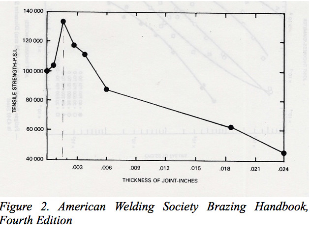
For silver, gold, copper and nickel braze filler metals suitable for vacuum brazing, the clearance should be 0.0260 to 0.05 mm (0.001 to 0.002-inch) at the brazing temperature. Vacuum has an effect on the design of clearances for a specific base and filler material. Vacuum brazing requires lower clearances than atmospheric type brazing to obtain optimum strength in the joint. In general, in vacuum furnace brazing of a vertical joint, a free flowing braze filler will flow out of the joint if the clearance is in excess of 0.076mm (0.003"). Larger clearances can be filled with fillers having a wide melting range. Clearance must be considered either at room temperature or at the brazing temperature. With similar metals of approximately equal mass, room temperature is suitable. Between similar metals clearance is easily maintained in assemblies where parts are a press or shrink fit. In some cases, it is necessary to fit spacer wires, shims, prick/punch marks, knurl, grit blast, etc., to ensure proper clearance for optimum results and flow into the joint.
Differential Metal Expansion (DME)
With dissimilar metals, the one with the highest expansion coefficient may tend to increase or decrease the clearance depending on relative positions and configurations of the joint [3]. Optimal gap clearance for BFM flow for dissimilar joint metal members is always specified at brazing temperature!
CALCULATIONS: Knowing the DME rates for the metals being joined, back-calculate from the brazing temperature down to room temperature (RT) to find RT clearance at brazing temperature [3].
When cooling down from the brazing temperature, stresses and strains are put on the joint. The joint either wants to open up and get larger on cooling (causing tensile stresses in the joint), that is least desirable as it may lead to cracks in the joint. Or it wants to contract and get smaller on cooling (resulting in compressive stresses in the joint) that is most desirable.
Joints should be designed for vacuum furnace brazing and if possible, braze filler should be pre-placed in the joint or adjacent to the heaviest member. This will minimise the tendency for the braze to melt and flow when the lightest member reaches the required temperature. Specific consideration must be given to expansion to obtain the correct joint clearance at the brazing temperature.
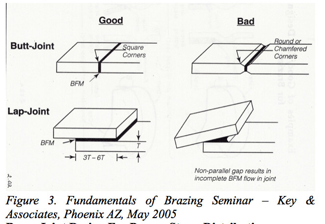
Overlap And Surface Flatness Brazing
Proper overlap length (lap-joints), flatness and squareness of joined members must be maintained in order to obtain quality joints (Ref. Figure 3). This is the formula to calculate the length of lap for flat joints [5]:
X = (Y ï T ï W) L
Where: X = Length of lap area
Y = Safety factor desired
T = Tensile strength of weakest member
W = Thickness of weakest member
L = Shear strength of brazing filler metal
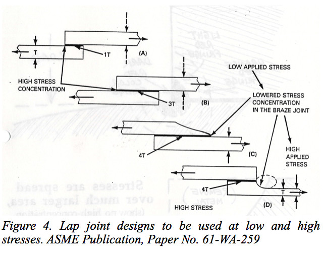
Braze Joint Design For Proper Stress Distribution
Lap joints can be designed to be fused at high and low stress. Flexure of the right member (Ref. in C and D in Figure 3) will distribute load through the base metal thus reducing the stress concentration and improving fatigue life of the brazement.
Effect Of Surface Roughness On Braze Joint Properties
Extensive testing over the years has shown that the best surface for brazing is the “as-received” surface roughness of the material coming into the shop. This as-received surface may be 32 RMS, 64 RMS or even 125 RMS or greater. Surface roughness adds surface area to the joint, which provides countless extra capillary paths for BFM to follow.
CAUTION 1: It is not recommended to polish the metal surface prior to brazing! This can destroy capillary path, and, with “metal-to-metal” pressed contact, could actually shut off capillary flow entirely. Figure 5 below shows what happens when an as-received metal surface (under high magnification) is placed together with “metal-to-metal” pressed contact [2].
CAUTION 2: It is strongly recommended to perform surface enhancement of the polished joint members prior to brazing by rough grit blasting using chilled cast iron, or stainless-steel grits (do not use of non-metallic media).
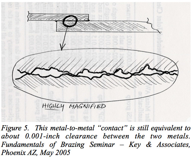
Note that the hills and valleys of the surface roughness still allow BFM to flow through the joint. This metal-to-metal “contact” is still equivalent to about a 0.001-inch clearance between the two braze joint metal members.
Cleaning Procedure Prior To Vacuum Brazing
Clean, oxide free surfaces are imperative to ensure sound brazed joints of uniform quality. Uniform capillary attraction may be obtained only when all grease, oil, dirt, and oxides have been removed from both the filler metal and the base metal before brazing. The choice of cleaning process depends on the following [2]:
- Nature of contamination
- Specific base metal to be cleaned
- Degree of cleanliness required for brazing
- Part configuration
- Need to remove or provide barrier for coating for undesirable element such as Al, Ti, N2 ,etc.,)
Chemical Cleaning Methods:
- Emulsion cleaning in insoluble hydrocarbons and water (good for removal of oils and cutting fluids)
- Cleaning in water-base alkaline cleaners (good for removal of oils and cutting fluids)
- Solvent cleaning in mineral spirits, alcohol, acetone, chlorinated hydrocarbons (good for removal of mineral oils and cutting fluids). Poor effect when used for removal of water-soluble oils.
- Vapor degreasing in trichlorethylene, trichloroethane, (excellent for removal of mineral oils and cutting fluids). Poor effect when used for removal of water-soluble oils.
Mechanical Cleaning Methods:
All parts shall be chemically cleaned to remove oils, dirt and greases prior to attempting one of these mechanical cleaning methods:
- Grit blasting using chilled cast iron, or stainless-steel grits or powders.
CAUTION: grit blasting with non-metallic materials (aluminium oxide, silicon carbide, etc.,) can ruin brazing!
- Machining or grinding is acceptable methods provided that joint clearances are not disturbed.
The ability to "wet" a surface and flow freely over it is the most important characteristic of any braze alloy. To secure good wet absolute cleanliness is essential. Once cleaned, components should not be handled more than necessary and then only when wearing cotton gloves. Delays between preparation and processing parts should be kept to a minimum. If there is a waiting time then bag, cover or place in an environmental cabinet.
Adequate time must be given to allow thorough purging of retorts before heating. With Push through Furnaces time must be given to allow the gas to displace any trapped air in boats before pushing the work into the hot section of the furnace.
The tendency for a braze alloy to spread can be assessed by measuring the advancing contact angle between the alloy and the parent material. Different braze and parent materials will behave differently together but cleanliness is very significant. Contact angle is also affected by surface roughness, and possibly time and temperature.
Brazing Filler Metal Selection
In order for satisfactory use under actual conditions, BFM must have the following characteristics:
- Ability to “wet” the base metal on which it is used.
- Suitable melting and flow properties to permit distribution by capillary attraction in properly prepared joints.
- Ability to make a strong, sound metallurgical bond to the base metal on which it is used.
- Must have chemical composition of sufficient homogeneity and stability to minimize separation by liquation under the brazing condition to be encountered. It is desirable that BFM would have a compatible chemical composition with the substrate [1,2, 4].
- BFM must be able to produce a braze joint that will meet the service requirements specified (e.g. strength, thermal cycling and fatigue, corrosion resistance, must withstand service temperature, shock and vibration).
Braze alloys are numerous and available in a variety of forms; wire, foil, strip, powder, paste, prefabs, transfer tape etc. The braze alloy type can dictate the method of assembly of a component and how it is applied.
The Pd, Au and Ag ranges being easily worked are widely available as wire, foil and performs. Solid forms are preferred since cycle times are kept to a minimum and preparation and assembly of parts is easier. Placement of the braze is consistent with none of the variances attributable to operators applying uneven amounts of braze paste.
Pastes are available for many of the common brazes and find common use with Ni and Co types which are not easy to workinto foil and wire. With pastes the organic binders must be allowed to dry before loading to the furnace. Heating must give time for binders to evolve slowly and steadily hence the common practice of an intermediate soak in the range 350°C to 450°C. With any binder there is always a risk of entrapmentand carbonaeous debris in the joint. Excessive spreading ofbraze will occur if evolution of the binder is too rapid.
Assembly & Fixturing For Brazing
Brazements should be designed so that the detail parts are self-fixturing and self-aligning where possible. The use of fixtures in the furnace increases the cost of processing and adds to distortion difficulties. In cases where self-jigging is not possible, brazements can be created by utilizing one of the following methods: tack welding, poke welding, gravity locating, swaging or stacking. It should be obvious that to obtain an adequate braze joint clean, oxide free surfaces of assembled work pieces are imperative. Further, maintaining a proper gap clearance is one of the most important issues in the assembly of parts for brazing.
When specific effects during brazing are to be obtained and/or parts configuration do not allow the use of a self- fixturing method, properly designed fixtures must be used. Fixtures must be capable of maintaining proper braze clearance, have dimensional stability, and have compatible coefficients of thermal expansion with parts being brazed.
Where fixtures are required, the design and material must conform to the following:
- Use thin sections consistent with rigidity and durability as required. Avoid heavy sections. The total weight of all fixtures shall not exceed 50% of the total weight of the assemblies being brazed per furnace run.
- Fixtures should be made from materials which are not reactive with the material of the assembly being brazed. Inconel 600, Alloy 230, MA956, Molybdenum and graphite are recommended fixture materials for vacuum brazing and heat treatment. These materials will maintain high strength in elevated temperatures and have good resistance to thermal shock.
- Avoid the use of dissimilar metals where differences in thermal expansion could affect assembly dimensions.
- Avoid the use of bolts and screws as they may relax upon heating or pressure welding in place.
- Fixtures must not interfere with the flow of cooling gas.
- Fixtures should be subjected to the brazing environment prior to use, to ensure stability and relieve stresses.
Pre-placed braze is placed within and covers the whole surface of the joint. This method is applicable to transfer tape, cut foils and performs.
Capillary placed externally to but in contact with the joint. On melting the braze is sucked into the joint. This method is suitable for wire and paste.
Where the complete periphery of the joint is visible, inspection is a straightforward case of looking for complete full fillet all round. When only one side of the joint is visible after assembly it is better to place the braze so capillaries towards those visible edges in order to be confident in the final result.
Vacuum Furnace Brazing Cycles
A properly designed vacuum brazing cycle (Ref. Figures 6 and 7) is a very critical step in the vacuum brazing process. The brazing cycle shall comprise the following segments:
Initial Pumpdown For easy-to braze materials (Ref. Figure 6) evacuating vacuum to 8 x 10⁻⁴ torr is sufficient; however, for difficult-to-braze materials (e.g. nickel-base superalloys containing appreciable amounts of aluminum and titanium), the furnace should be pumped down to below 5 x 10⁻⁴ torr before commencing heating.

Initial Heating Ramp The initial ramp should be 20º to 30º F/minute. Faster rates are not recommended because:
- part distortion may occur
- brazing slurry application may spall off
- With large loads (containing appreciable amount of brazing slurry) excessive outgassing will likely occur
Cement Burn-Off For critical materials (e.g. nickel-base superalloys) particularly, with heavily applicated parts (e.g. surface braze build-up) a burn off soak (Ref. Figure 7) is strongly recommended to avoid too high a pressure rise.
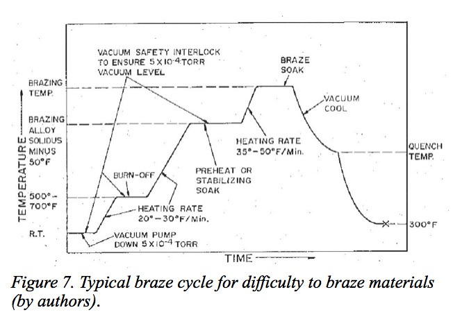
Stabilizing Soak A soak temperature shall be about 50ºF below solidus temperature of the brazing slurry for duration of 15 to 30 minutes, or until the pressure drops below the desired level, whichever is longer. This soak serves two purposes:
- It allows the temperature throughout the load to equalize so all parts in the load will reach brazing temperature at approximately the same time during the next heating cycle
- It ensures that vacuum pressure levels are low enough before proceeding (ramping) to brazing temperature
Heating Ramp to Brazing Temperature The final heating rate to brazing temperature is very critical. The rate must be fast enough to avoid excessive liquidation of the brazing alloy and subsequent alloying with and erosion of the base metal. For thin materials (e.g. 0.010-inch thickness or less) heating rates of 50º to 75º F/minute are essential. Rates of 30º to 50º F/minute are the most frequently used in the industry.
Brazing Temperature It is desirable to use the lowest brazing temperature within the recommended brazing range consistent with producing a satisfactory joint. In some applications minimum brazing temperatures are essential:
- when using pure copper brazing filler
- to fill large gaps with wide gap nickel alloys
- when brazing very thin materials
NOTE: For extremely thin metal, fillet type joint (e.g. honeycomb seals), a brazing temperature is equal or even slightly below the liquidus temperature in order to avoid excessive flow and erosion.
Brazing Soak In general, time at brazing temperature should be long enough to ensure that all sections of a work piece and all parts within the load reach the desired brazing temperature.
NOTE: Brazing temperature and brazing time are considered as a “critical event”. It is strongly recommended that Guaranteed Soak Point be used in the program.
Attack of component material by reaction with the braze filler, i.e. erosion, is related to diffusion but undesirable. Both can be avoided by keeping times at soak and brazing temperatures to a minimum and by choosing appropriate temperatures
Cooling From Brazing Temperature For materials that do not require solution heat treatment or hardening, it is recommended that the load be vacuum cooled from brazing temperature to a temperature at least 50ºF below the solidus temperature of the brazing slurry, before initiating the gas quenching system. If the part requires heat treatment from brazing temperature, then the gas quench must be initiated at the end of the brazing soak period.
Unloading the Furnace In theory parts can be unloaded when they are below 400ºF without discoloration. However, to ensure that there is no possibility of discoloration on critical, heavier parts, it is recommended that all load thermocouples be below 200ºF before opening the furnace. Brazed joints may be reworked by brazing to the original, qualified brazing procedure specification.
Vacuum Equipment Qualification
And Periodic Testing/Calibration
The vacuum furnace used for brazing operations requires adherence to specific industry standards for brazing processes. Before use, vacuum furnaces should be checked for instrument accuracy, temperature accuracy, temperature uniformity, and leak rate.
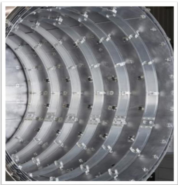
Figure 8 Vacuum Brazing Furnace with All Metal Hot Zone
Vacuum furnaces for brazing below 2000°F (1093°C) that are using workload thermocouples should be qualified every six-months, and 90 days for those furnaces not using workload thermocouples. Vacuum furnaces used for brazing above 2000°F (1093°C) should be qualified not to exceed three months when working thermocouples are being used, and 30 days for those furnaces that do not use workload thermocouples.
Furnace Instrument Accuracy Check
This check consists of a visual comparison between the temperature indicator/controller and the furnace chart recorder readouts. Both must be within specified furnace system temperature accuracy (usually ±1°C).
Furnace System Accuracy Test
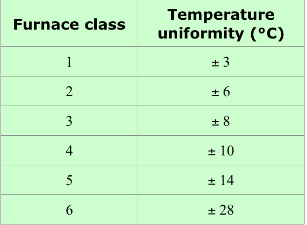
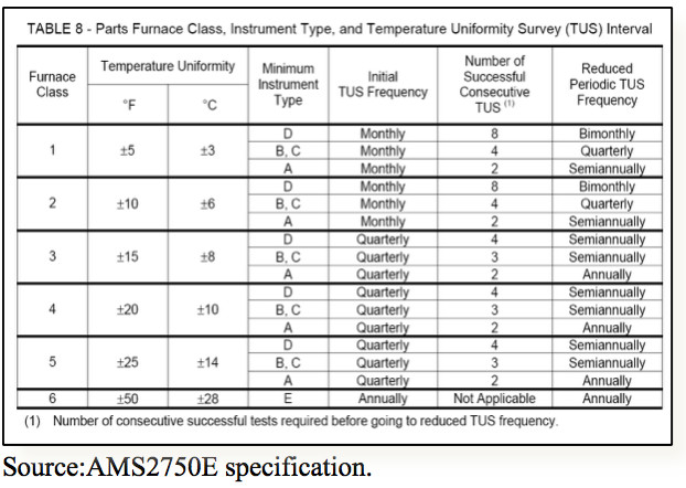
In the area of requirements related to the accuracy of temperature regulation and uniformity, standard AMS2750 (Aerospace Material Specification) is used most often. It was issued by SAE (Society of Automotive Engineers) in 1980. The most recent revision AMS275E was published July 2012. It introduces stricter requirements for temperature measurement, inspection and recording equipment in furnaces installed after September 2006. The furnace system accuracy test shall be accomplished by inserting the temperature-sensing element within a maximum of three inches (or less) of the furnace control thermocouple. The furnace system accuracy should be measured every 30 days by the installation of a probe thermocouple in the hot zone within 3 inches (76 mm) from the furnace control thermocouple. The variation shall be not greater than +/- 0.75% of probe temperature. The probe temperature should be taken within 200F (93ºC) of the lowest and highest qualification temperature of the furnace. To avoid excessive heat losses (heat draft) it is recommended to insulate the controlling thermocouple between the hot zone and vacuum vessel. The table below shows the new temperature uniformity requirements according to AMS2750E.
In its revised version, standard AMS2750E imposes upon furnace users the duty of periodically inspecting the accuracy of the temperature measuring system. The SAT (System Accuracy Test) tests are done with a frequency that depends upon the furnace class and the type of measuring equipment used in it ("A" or "E"). In the case of the vacuum furnace type class 2 instruments D, the SAT test should be performed weekly. The below table describes frequency of System Accuracy Test intervals according to instrument type and furnace class.

Furnace Temperature Uniformity Survey
Temperature uniformity should be performed without a load.
No less than nine thermocouples should be used for furnaces with hot zones more that 10 cubic feet. Thermocouples should be located symmetrically within hot zone. The qualification should be performed at the lowest and highest operating temperature of the vacuum furnace and at an intermediate temperature such that the difference between qualification temperatures is not greater than 600°F (316°C). For vacuum furnaces operating above required range of less than 200°F (93°C) only the lowest and the highest temperature should be used. The temperature should be recorded at two minutes interval starting 100°F (38°C) below the first set point and continued recorded at least 30 minutes after controlling thermocouple indicates that hot zone has reached thermal equilibrium. According to AMS2750E Vacuum
Level during TUS” shall be run at the lowest vacuum level
used in production, but need not be less than 1 micron Hg.” Most vacuum furnaces are designed class 2 and achieve -±6°C/±10ºF or better temperature uniformity.
Leak Rate Check
The leak rate check shall be conducted weekly and should be measured in an empty, clean, cold and out gassed furnace and should not exceed 10 microns per hour for general applications, or 5 microns per hour for critical applications. The furnace burnout cycle shall be done prior to conducting the leak rate check. The burnout temperature shall be 100∞F higher than the highest temperatures used during the previous week. The leak rate should be measured after furnace has reached less than 5x10⁻⁴ Torr. A more accurate leak check that takes into consideration the vacuum chamber size can be done according to the following procedure:
Q=(P2-P1) x V/t
Q – Leak Rate
P2 – vacuum after survey end
P1 – vacuum on the start of survey
V – volume of the furnace vessel in litres
T – survey time (no less that 60 minutes)
Most good furnaces have leak rate around 1 x 10⁻³ Torr x l/s) or better.
Workload Thermocouples
The thermocouple is a critical part of furnace control. Obviously, if we are to get meaningful readings, then sensible positioning is essential. Workload control thermocouples shall be specify by ASTM E230 specification. They shall be calibrated by comparison to a known calibrated test instrument.
Thermocouple types are chosen to suit the process, especially temperature capability. There are 3 types in common use: Type K (chromel-alumel) for use up to 1150°C (2100°F), Type S (platinum-platinum/rhodium) for use up 1600°C (2900°F) and W3 (tungsten/26%rhenium - tungsten/3%rhenium) for use up to 2000°C (3600°F).
Type K is well known and widely used, but they are susceptible to drift at elevated temperatures. Accuracy and reliability become increasingly poor with exposure to sustained higher temperatures, especially above 1150°C (2000°F). They are also sensitive to the atmosphere in which they are used. Beaded types should be used in oxidizing conditions. Mildly oxidizing or reducing atmospheres can lead to Cr loss and lower readings of EMF and error. Re-use of type K thermocouples shall be limited to the following equation:
U = A + 2*B + 7*C≤ 30
A = a number of usages below 1200°F
B = a number of usages below 2000°F
C = a number of usages over 2000°F
The alternative to K which avoids these problems without the expense of Types R or S is Type N. Susceptibility to drift is much reduced, accuracy better (±1.5°C up to 1250°C) and with a continuous temperature capability of 1250°C (2200°F). Use of Type N thermocouples in vacuum furnaces has proved to be very practical. Experience has shown that Type N thermocouples last much longer without failure than Type K thermocouples. Yet, Type N thermocouples require re-calibration or replacement every three months.
Load thermocouples need to be placed in such a way that they reflect true load behavior. The hot junction should be placed in a hole in the component or fixture by preference. If this is not feasible, then in a block of material placed in the load and typical of the component section thickness. In any case, the hot junction should not see direct radiation from heating elements or hot zone insulation.
Vacuum Level During Brazing
The ability to "wet" a surface and flow freely over it is the most important characteristic of any braze alloy. To secure good wetting, parts and vacuum furnace cleanliness and proper vacuum level are essential. When heated, parts require protection. Adequate time must be given to allow thorough purging and evacuation before heating starts.
To achieve the high vacuum necessary and to ensure that it is maintained through the useful life, it is necessary to outgas/clean the vacuum hot zone periodically. Together with the necessity for low vacuum leak rate 1x10⁻³ Torr/l-s or less that 5 microns per hour vacuum tightness is very important to achieve quality brazing.
A vacuum level of 5 micron or less should be properly controlled. A Dew Point of -55°C/-67°F (10-2 Torr) is required to braze stainless steel. Oxygen must also be controlled to suit the process and materials processed. Vacuum conditions in most cases reduce oxides so braze fillers can wet and flow over the surfaces of the cleaned metal. For special applications, with more demanding brazing specifications in the level range of 10–7 Torr, Turbomolecular or Cryopumps are used.
Cooling Gases
Cooling gases that are used to shorten the brazing cycle and achieve proper metallurgical properties should be of high purity to prevent the formation of oxides.
Inert cooling gases
Argon - 99.999 percent purity with dew point lower than
–60ºF inhibits evaporation and forms no compound.
Nitrogen 99.9995 percent purity with dew point lower than
–60ºF- should be acceptable, but should be avoided if harmful formation of nitrides occurs.
Inspection After Vacuum Brazing
The quality control system should be adequate for general and critical applications. Knowledgeable inspection of finished brazed assemblies shall use adequate inspection techniques as applicable to a particular application (general or critical).
Visual Inspection and FPI (Flourescent Penetrant Inspection)
Visual inspection is (and should be!) the widely used NDT methods. FPI shall be used for machined surfaces only. Parts should be inspected for the following conditions:
- cracks or voids in brazed joint or adjacent base material
- surface porosity
- completeness of brazed joint band (excluding the fillet) around the circumference or along braze application (visual only)
- freedom from excess braze filler material on surface of assembled parts (visual only)
Radiographic Examination
Radiography (or ultrasonic inspection) shall be used for braze joints Class A to detect subsurface and/or internal defects. Special techniques are required to reliably inspect joints of varying thickness. Multiple views and careful interpretation is required.
Some of the Non-Destructive Testing (NDT) methods are being used improperly. FPI technique is limited to inspect machined surfaces only, but it is being used to detect defects in braze joint fillets. Similarly, many braze joints shall not be radiographically inspected because this technique requires sensitivities that are difficult to achieve (better than 2%) [2].